![[VerilogHDL] UpCounter, 디버깅, UART Tx](https://img1.daumcdn.net/thumb/R750x0/?scode=mtistory2&fname=https%3A%2F%2Fblog.kakaocdn.net%2Fdn%2FrNZdr%2FbtsHt4GKhkZ%2FSqEK0mIH4LejNPLqR0OIQK%2Fimg.png)

1. FSM - UpCounter

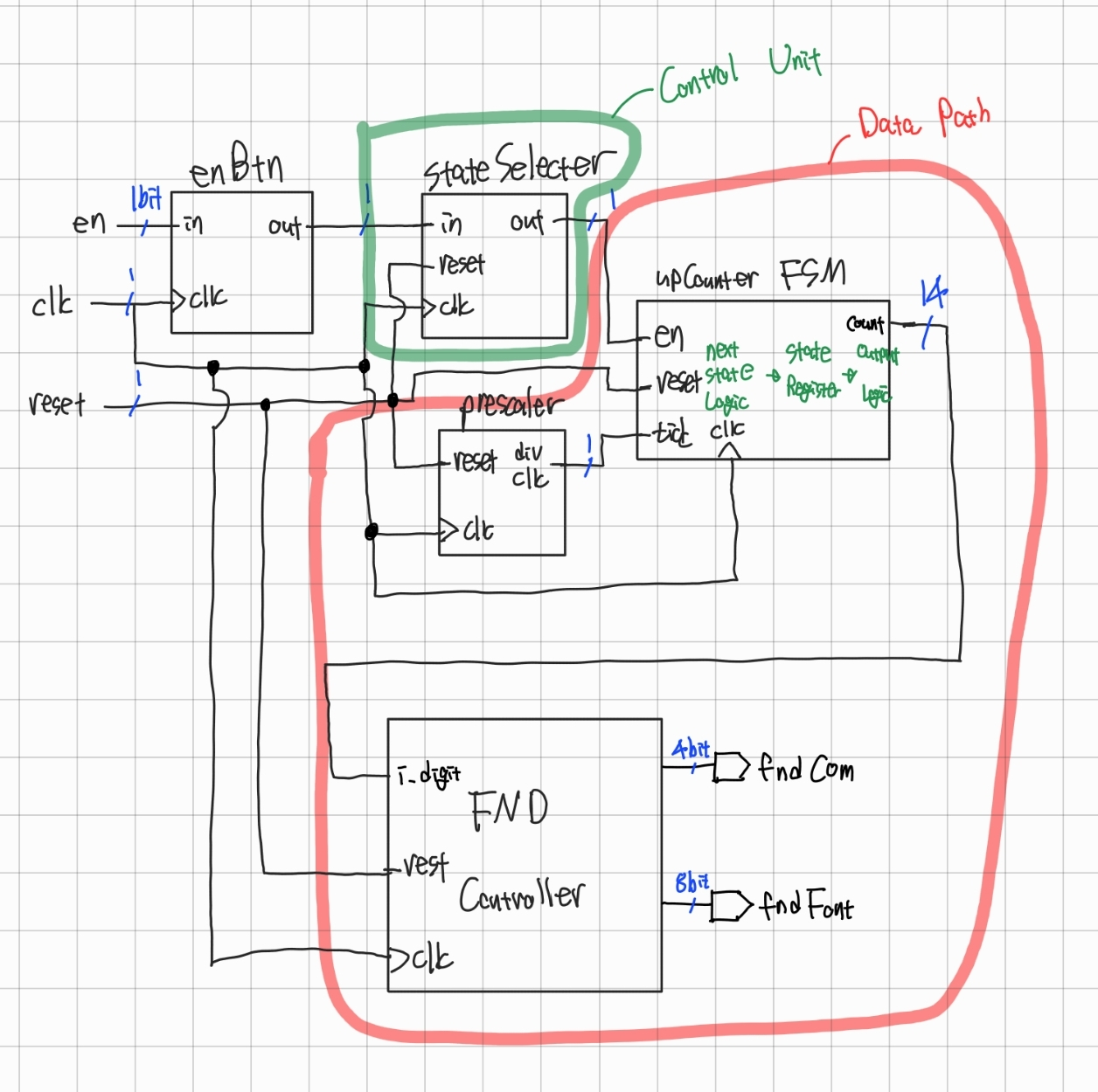
구현
`timescale 1ns / 1ps
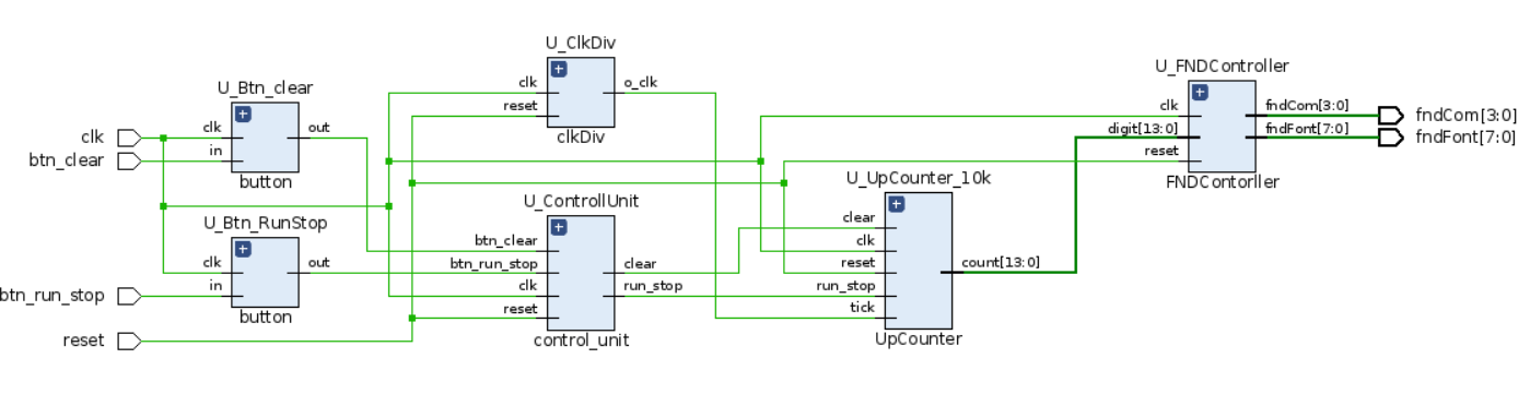
module top (
input clk,
input reset,
input btn_run_stop,
input btn_clear,
output [3:0] fndCom,
output [7:0] fndFont
);
wire w_div_clk;
wire w_run_stop, w_clear;
wire [13:0] w_digit;
clkDiv #(
.HERZ(1000)
) U_ClkDiv (
.clk (clk),
.reset(reset),
.o_clk(w_div_clk)
);
UpCounter U_UpCounter_10k (
.clk(clk),
.reset(reset),
.tick(w_div_clk),
.run_stop(w_run_stop),
.clear(w_clear),
.count(w_digit)
);
FNDContorller U_FNDController (
.reset(reset),
.clk (clk),
.digit(w_digit),
.fndFont(fndFont),
.fndCom (fndCom)
);
wire w_btn_run_stop, w_btn_clear;
button U_Btn_RunStop (
.clk(clk),
.in (btn_run_stop),
.out(w_btn_run_stop)
);
button U_Btn_clear (
.clk(clk),
.in (btn_clear),
.out(w_btn_clear)
);
control_unit U_ControllUnit (
.clk(clk),
.reset(reset),
.btn_run_stop(w_btn_run_stop),
.btn_clear(w_btn_clear),
.run_stop(w_run_stop),
.clear(w_clear)
);
endmodule`timescale 1ns / 1ps
module control_unit (
input clk,
input reset,
input btn_run_stop,
input btn_clear,
output run_stop,
output clear
);
parameter STOP = 2'd0, RUN = 2'd1, CLEAR = 2'd2;
reg [1:0] state, state_next;
reg run_stop_reg, run_stop_next, clear_reg, clear_next;
assign run_stop = run_stop_reg;
assign clear = clear_reg;
// state register
always @(posedge clk, posedge reset) begin
if (reset) begin
state <= STOP;
run_stop_reg <= 1'b0;
clear_reg <= 1'b0;
end else begin
state <= state_next;
run_stop_reg <= run_stop_next;
clear_reg <= clear_next;
end
end
//next state combinational logic
always @(*) begin
state_next = state;
case (state)
STOP: begin
if (btn_run_stop) state_next = RUN;
else if (btn_clear) state_next = CLEAR;
else state_next = STOP;
end
RUN: begin
if (btn_run_stop) state_next = STOP;
else state_next = RUN;
end
CLEAR: begin
state_next = STOP;
end
endcase
end
// output combinational logic
always @(*) begin
case (state)
STOP: begin
run_stop_next = 1'b0;
clear_next = 1'b0;
end
RUN: begin
run_stop_next = 1'b1;
clear_next = 1'b0;
end
CLEAR: begin
run_stop_next = 1'b0;
clear_next = 1'b1;
end
endcase
end
endmodule`timescale 1ns / 1ps
module UpCounter (
input clk,
input reset,
input tick,
input run_stop,
input clear,
output [13:0] count
);
reg [13:0] counter_reg, counter_next;
assign count = counter_reg;
always @(posedge clk, posedge reset) begin
if (reset) begin
counter_reg <= 0;
end else begin
counter_reg <= counter_next;
end
end
always @(*) begin
counter_next = counter_reg;
if (tick && run_stop) begin
if (counter_reg == 9999) begin
counter_next = 0;
end else begin
counter_next = counter_reg + 1;
end
end else if (clear) begin
counter_next = 0;
end
end
endmodule
결과
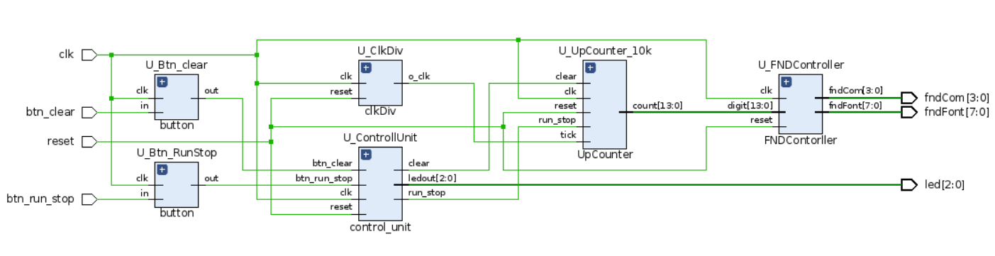
1-1. 각 state의 LED 점등 추가
구현
[Controll Unit]
`timescale 1ns / 1ps

module control_unit (
    input clk,
    input reset,
    input btn_run_stop,
    input btn_clear,

    output run_stop,
    output clear,
    output [2:0] ledout
);

    parameter STOP = 2'd0, RUN = 2'd1, CLEAR = 2'd2;
    reg [1:0] state, state_next;
    reg run_stop_reg, run_stop_next, clear_reg, clear_next;
    reg [2:0] ledout_reg, ledout_next;

    assign run_stop = run_stop_reg;
    assign clear = clear_reg;
    assign ledout = ledout_reg;

    // state register
    always @(posedge clk, posedge reset) begin
        if (reset) begin
            state <= STOP;
            run_stop_reg <= 1'b0;
            clear_reg <= 1'b0;
            ledout_reg <= 1'b000;
        end else begin
            state <= state_next;
            run_stop_reg <= run_stop_next;
            clear_reg <= clear_next;
            ledout_reg <= ledout_next;
        end
    end

    // next state combinational logic
    always @(*) begin
        state_next = state;
        case (state)
            STOP: begin
                if (btn_run_stop) state_next = RUN;
                else if (btn_clear) state_next = CLEAR;
                else state_next = STOP;
            end
            RUN: begin
                if (btn_run_stop) state_next = STOP;
                else state_next = RUN;
            end
            CLEAR: begin
                state_next = STOP;
            end
        endcase
    end

    // output combinational logic
    always @(*) begin
        run_stop_next = 1'b0;
        clear_next = 1'b0;
        ledout_next = 3'b000;
        case (state)
            STOP: begin
                run_stop_next = 1'b0;
                ledout_next = 3'b001;
            end
            RUN: begin
                run_stop_next = 1'b1;
                ledout_next = 3'b010;
            end
            CLEAR: begin
                clear_next = 1'b1;
                ledout_next = 3'b100;
            end
        endcase
    end
endmodule
[top module]
`timescale 1ns / 1ps

module top (
    input clk,
    input reset,
    input btn_run_stop,
    input btn_clear,

    output [3:0] fndCom,
    output [7:0] fndFont,
    output [2:0] led
);

    wire w_div_clk;
    wire w_run_stop, w_clear;
    wire [13:0] w_digit;

    clkDiv #(
        .HERZ(100)
    ) U_ClkDiv (
        .clk  (clk),
        .reset(reset),

        .o_clk(w_div_clk)
    );

    UpCounter U_UpCounter_10k (
        .clk(clk),
        .reset(reset),
        .tick(w_div_clk),
        .run_stop(w_run_stop),
        .clear(w_clear),

        .count(w_digit)
    );

    FNDContorller U_FNDController (
        .reset(reset),
        .clk  (clk),
        .digit(w_digit),

        .fndFont(fndFont),
        .fndCom (fndCom)
    );

    wire w_btn_run_stop, w_btn_clear;

    button U_Btn_RunStop (
        .clk(clk),
        .in (btn_run_stop),

        .out(w_btn_run_stop)
    );

    button U_Btn_clear (
        .clk(clk),
        .in (btn_clear),

        .out(w_btn_clear)
    );

    control_unit U_ControllUnit (
        .clk(clk),
        .reset(reset),
        .btn_run_stop(w_btn_run_stop),
        .btn_clear(w_btn_clear),

        .run_stop(w_run_stop),
        .clear(w_clear),
        .ledout(led)
    );
endmodule`timescale 1ns / 1ps
module control_unit (
input clk,
input reset,
input btn_run_stop,
input btn_clear,
output run_stop,
output clear,
output led_stop,
output led_run,
output led_clear
//output [2:0] ledout
);
parameter STOP = 2'd0, RUN = 2'd1, CLEAR = 2'd2;
reg [1:0] state, state_next;
reg run_stop_reg, run_stop_next, clear_reg, clear_next;
//reg [2:0] ledout_reg, ledout_next;
assign run_stop = run_stop_reg;
assign clear = clear_reg;
//assign ledout = ledout_reg;
// state register
always @(posedge clk, posedge reset) begin
if (reset) begin
state <= STOP;
run_stop_reg <= 1'b0;
clear_reg <= 1'b0;
end else begin
state <= state_next;
run_stop_reg <= run_stop_next;
clear_reg <= clear_next;
end
end
// next state combinational logic
always @(*) begin
state_next = state;
case (state)
STOP: begin
if (btn_run_stop) state_next = RUN;
else if (btn_clear) state_next = CLEAR;
else state_next = STOP;
end
RUN: begin
if (btn_run_stop) state_next = STOP;
else state_next = RUN;
end
CLEAR: begin
state_next = STOP;
end
endcase
end
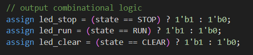
// output combinational logic
assign led_stop = (state == STOP) ? 1'b1 : 1'b0;
assign led_run = (state == RUN) ? 1'b1 : 1'b0;
assign led_clear = (state == CLEAR) ? 1'b1 : 1'b0;
always @(*) begin
run_stop_next = 1'b0;
clear_next = 1'b0;
//ledout_next = 3'b000;
case (state)
STOP: begin
run_stop_next = 1'b0;
//ledout_next = 3'b001;
end
RUN: begin
run_stop_next = 1'b1;
//ledout_next = 3'b010;
end
CLEAR: begin
clear_next = 1'b1;
//ledout_next = 3'b100;
end
endcase
end
endmodule
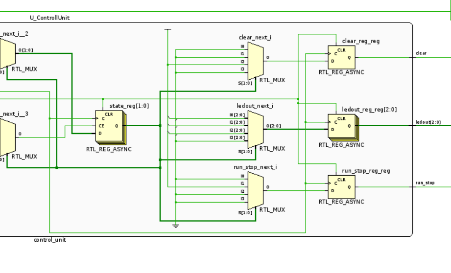
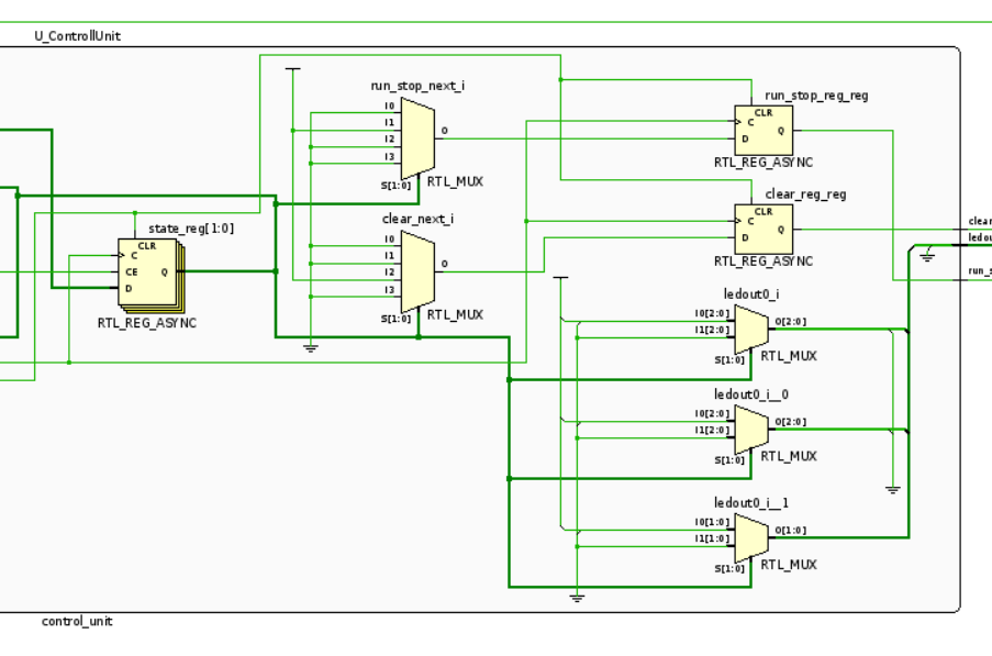
동작 결과는 똑같으나 ver.2 에서는 Latch를 줄이고 대신 MUX를 사용
결과
2. 디버깅
ILA Debug 적용
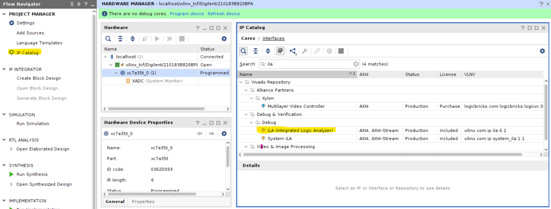
세팅
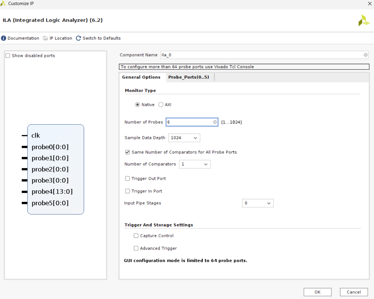
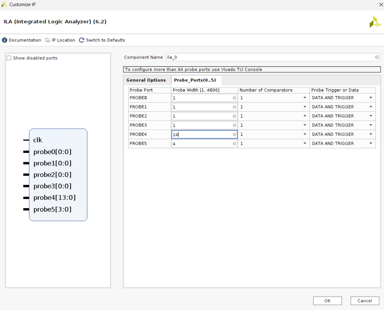
- Number of Probes : 확인하고자 하는 포트 개수
- Sample Data Depth : 몇 클럭을 디버깅할 것인가?
top module에 붙여넣기

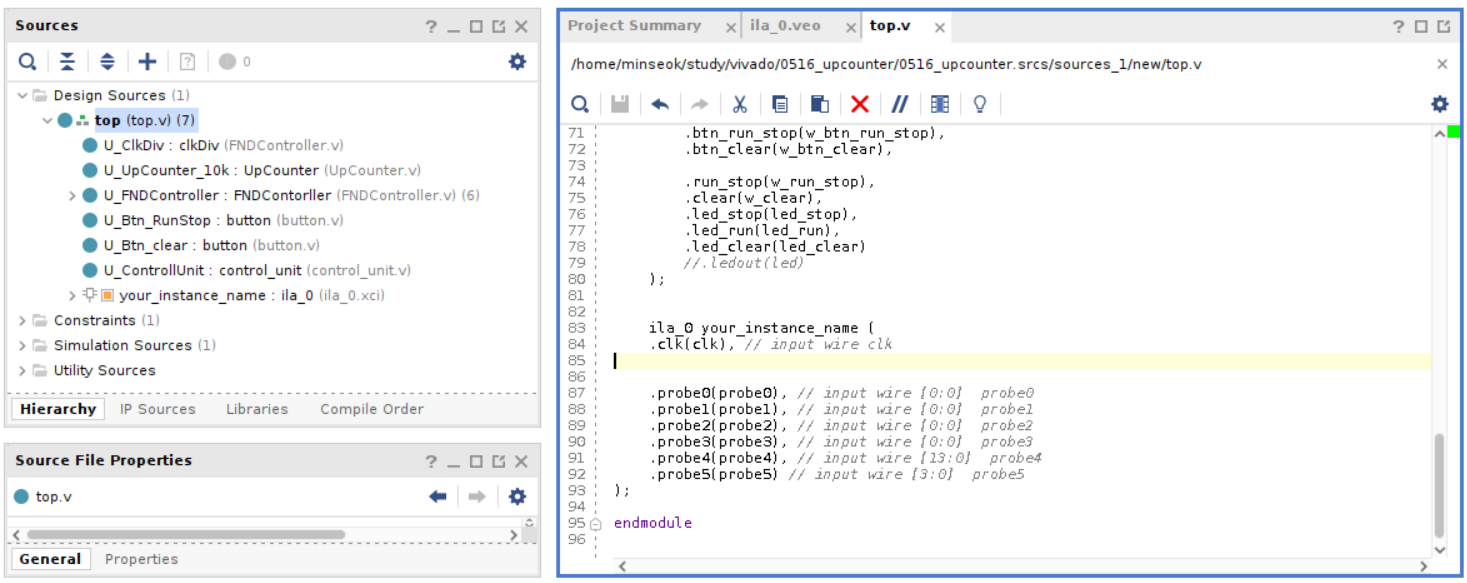
    ila_0 your_instance_name (
        .clk(clk),  // input wire clk

        .probe0(w_btn_run_stop),  // input wire [0:0]  probe0
        .probe1(w_btn_clear),  // input wire [0:0]  probe1
        .probe2(w_run_stop),  // input wire [0:0]  probe2
        .probe3(w_clear),  // input wire [0:0]  probe3
        .probe4(w_digit),  // input wire [13:0]  probe4
        .probe5(fndCom)   // input wire [3:0]  probe5
);- 해당 포트에 프로브를 찍는 것과 같음
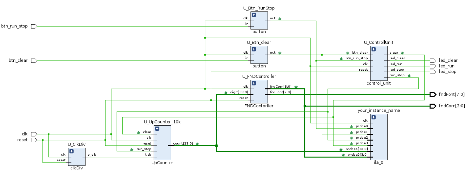
- RTL Schematic을 확인해보면 probe를 찍은 포트에 벌레 문양이 생김
확인하기
1. bitstream 다운로드
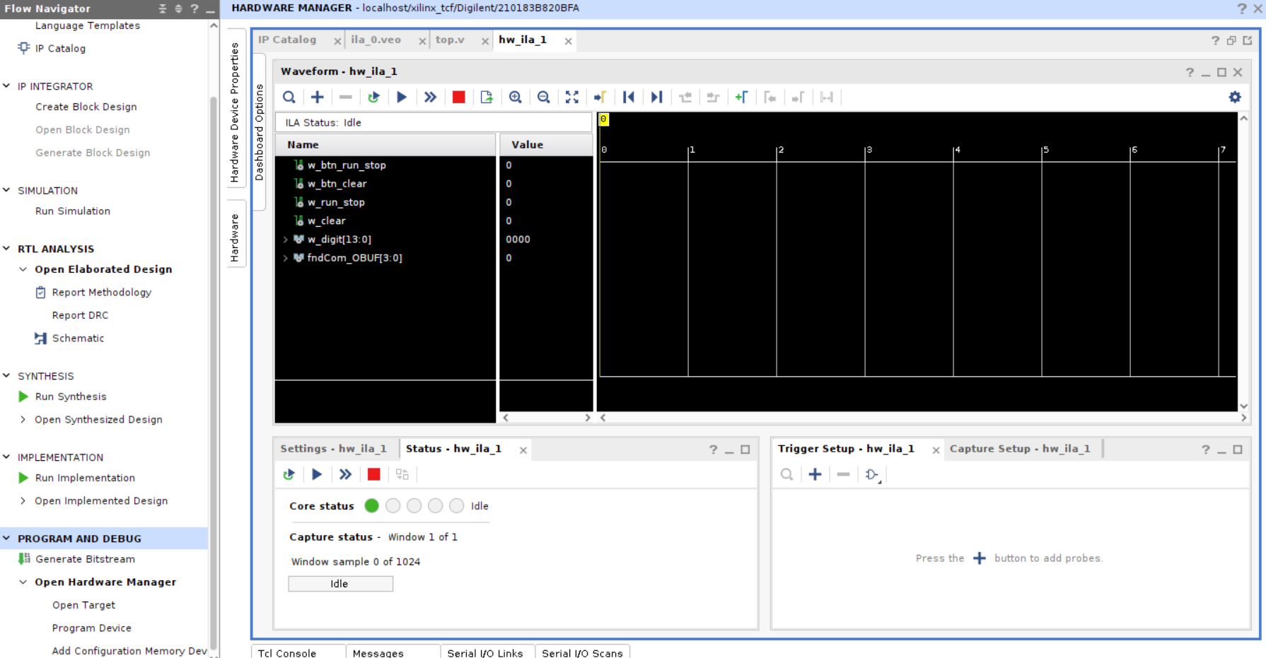
2. 원하는 프로브 선택
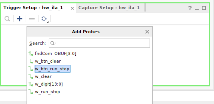
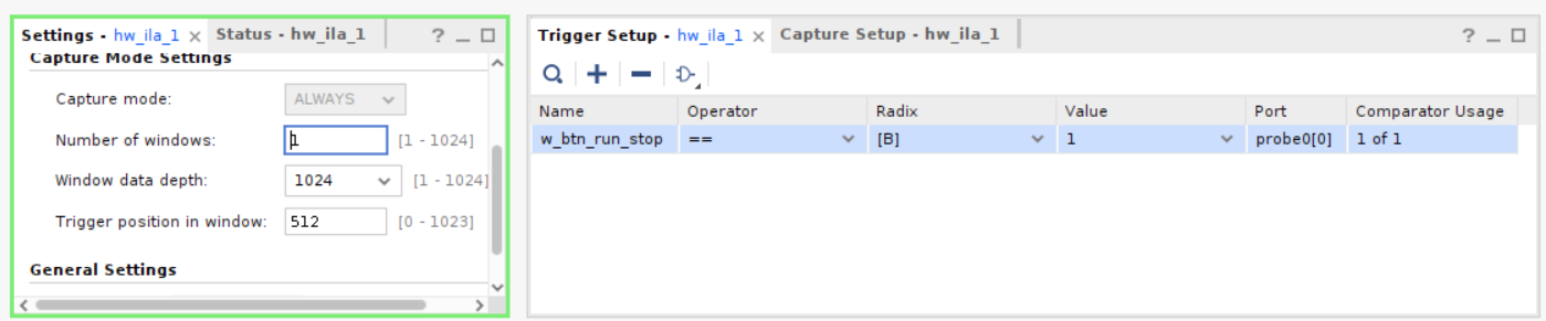
- run_stop 버튼이 1이 되면 캡쳐
- Number of windows : 몇번 캡쳐할 것인가?

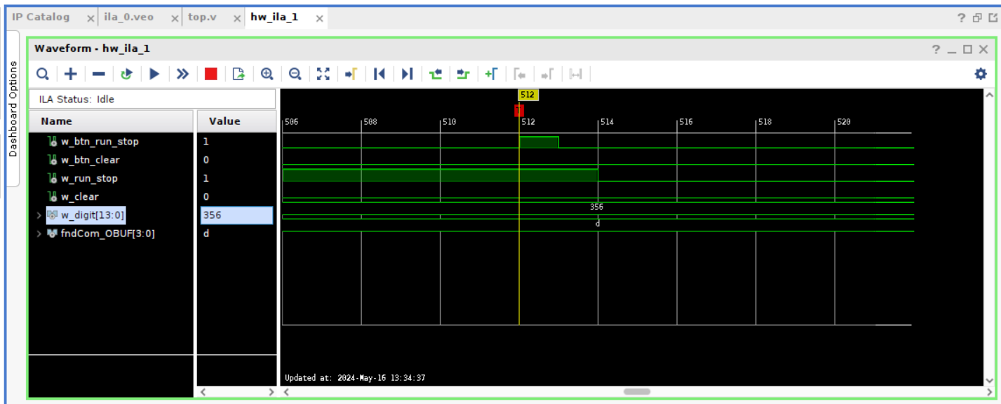
- 좌측 하단 RUN 버튼 누르고 보드의 run_stop 버튼을 누르면 위와 같이 디버깅 결과가 나옴
- 오른쪽 사진은 run → stop으로 바뀌었을 때 캡쳐
- FND 출력 356을 디버깅 화면에서도 확인할 수 있음
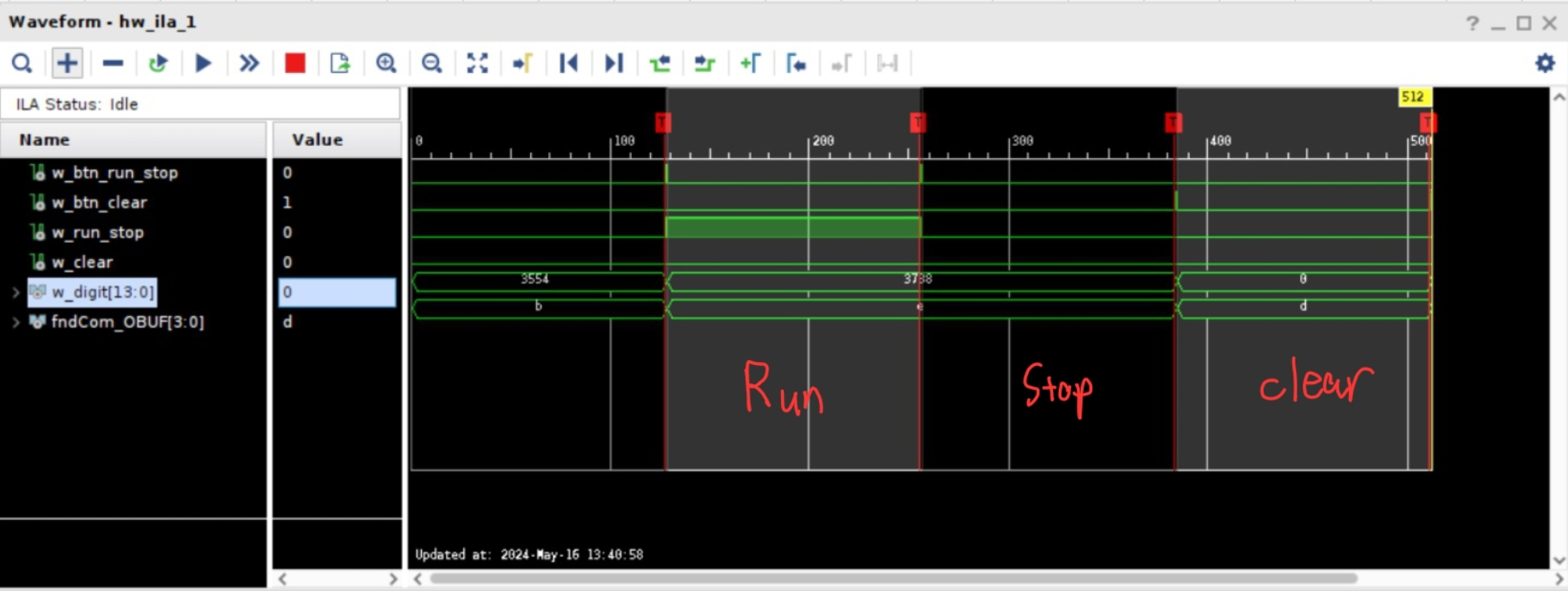
여러개 프로브 디버깅
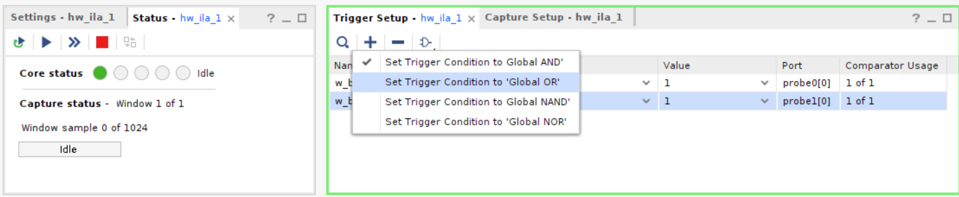
run & stop & clear 확인
전체 코드
GitHub - k1minseok/Verilog_UpCounter_0514: 10k UpCounter FSM Architecture & Input Reset, En Button & Output to FND
10k UpCounter FSM Architecture & Input Reset, En Button & Output to FND - GitHub - k1minseok/Verilog_UpCounter_0514: 10k UpCounter FSM Architecture & Input Reset, En Button & Outpu...
github.com
3. UART Tx
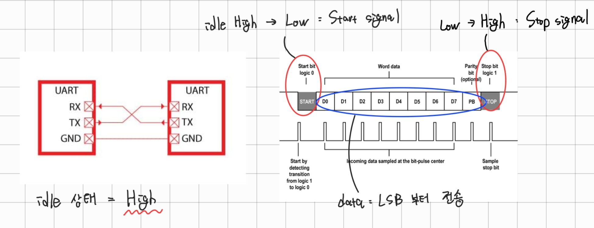
Transmitter
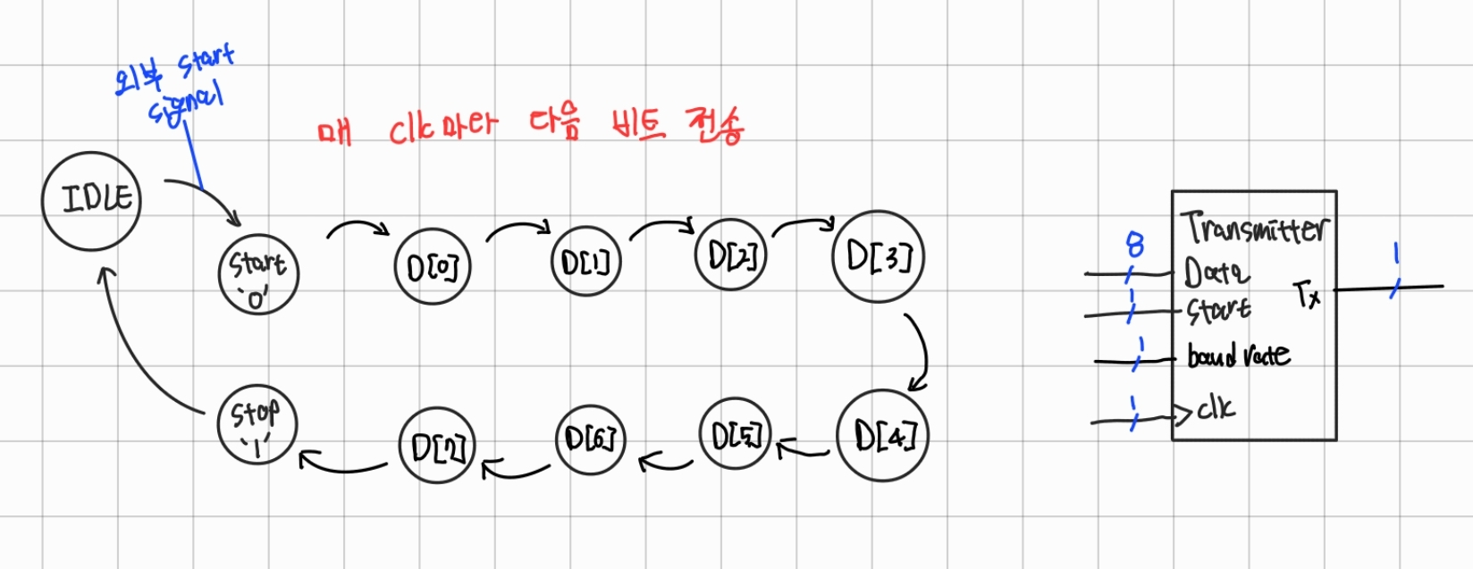
구현
`timescale 1ns / 1ps


module uart (
    input clk,
    input reset,
    input start,
    input [7:0] tx_data,

    output txd,
    output tx_done
);

    wire w_br_tick;

    baudrate_generator U_BR_Gen (
        .clk  (clk),
        .reset(reset),

        .br_tick(w_br_tick)
    );

    transmitter U_TxD (
        .clk(clk),
        .reset(reset),
        .start(start),
        .br_tick(w_br_tick),
        .data(tx_data),

        .tx(txd),
        .tx_done(tx_done)
    );
endmodule


module baudrate_generator (
    input clk,
    input reset,

    output br_tick
);

    reg [$clog2(100_000_000/100_000_00)-1:0] counter_reg, counter_next;
    reg tick_reg, tick_next;

    assign br_tick = tick_reg;

    always @(posedge clk, posedge reset) begin
        if (reset) begin
            counter_reg <= 0;
            tick_reg <= 1'b0;
        end else begin
            counter_reg <= counter_next;
            tick_reg <= tick_next;
        end
    end

    always @(*) begin
        counter_next = counter_reg;
        if (counter_reg == 100_000_000 / 100_000_00 - 1) begin  // baudrate 9600Hz
            counter_next = 0;
            tick_next = 1'b1;
        end else begin
            counter_next = counter_reg + 1;
            tick_next = 1'b0;
        end
    end
endmodule


module transmitter (
    input clk,
    input reset,
    input start,
    input br_tick,
    input [7:0] data,

    output tx,
    output tx_done      // 출력 완료 신호
);

    localparam IDLE = 0, START = 1, STOP = 10;
    localparam D0 = 2, D1 = 3, D2 = 4, D3 = 5, D4 = 6, D5 = 7, D6 = 8, D7 = 9;

    reg [3:0] state, state_next;
    reg [7:0] r_data;
    reg tx_reg, tx_next;
    reg tx_done_reg, tx_done_next;


    assign tx = tx_reg;
    assign tx_done = tx_done_reg;


    // state register
    always @(posedge clk, posedge reset) begin
        if (reset) begin
            state  <= IDLE;
            tx_reg <= 1'b0;
            tx_done_reg <= 1'b0;
        end else begin
            state  <= state_next;
            tx_reg <= tx_next;
            tx_done_reg <= tx_done_next;
        end
    end


    // next state combinational logic
    always @(*) begin
        state_next = state;

        case (state)
            IDLE: if (start) state_next = START;
            START: if (br_tick) state_next = D0;
            D0: if (br_tick) state_next = D1;
            D1: if (br_tick) state_next = D2;
            D2: if (br_tick) state_next = D3;
            D3: if (br_tick) state_next = D4;
            D4: if (br_tick) state_next = D5;
            D5: if (br_tick) state_next = D6;
            D6: if (br_tick) state_next = D7;
            D7: if (br_tick) state_next = STOP;
            STOP: if (br_tick) state_next = IDLE;
        endcase
    end


    // output state combinational logic
    always @(*) begin
        tx_next = tx_reg;
        tx_done_next = 1'b0;
        case (state)
            IDLE: tx_next = 1'b1;
            START: begin
                tx_next = 1'b0;
                r_data  = data;
            end
            D0:   tx_next = r_data[0];
            D1:   tx_next = r_data[1];
            D2:   tx_next = r_data[2];
            D3:   tx_next = r_data[3];
            D4:   tx_next = r_data[4];
            D5:   tx_next = r_data[5];
            D6:   tx_next = r_data[6];
            D7:   tx_next = r_data[7];
            STOP: begin
                tx_next = 1'b1;
                if(state_next == IDLE) tx_done_next = 1'b1;
            end
        endcase
    end
endmodule
GitHub - k1minseok/Verilog_UARTtx_0516: UART transmitter & Input Reset, Start Button
UART transmitter & Input Reset, Start Button. Contribute to k1minseok/Verilog_UARTtx_0516 development by creating an account on GitHub.
github.com
Simulation
`timescale 1ns / 1ps


module test_bench ();

    reg clk;
    reg reset;
    reg start;
    reg [7:0] tx_data;

    wire txd;
    wire tx_done;

    uart dut (
        .clk(clk),
        .reset(reset),
        .start(start),
        .tx_data(tx_data),

        .txd(txd),
        .tx_done(tx_done)
    );


    always #5 clk = ~clk;

    initial begin
        clk = 1'b0;
        reset = 1'b1;
        start = 1'b0;
        tx_data = 0;
    end

    initial begin
        #20 reset = 1'b0;
        #20 tx_data = 8'haf; start = 1'b1;
        #10 start = 1'b0;
    end

endmodule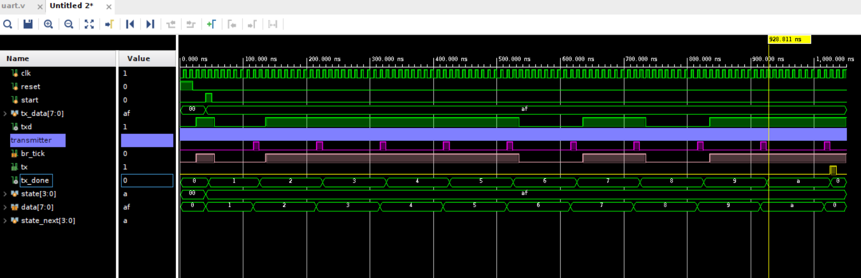
3-1. Transmit test
board → computer
`timescale 1ns / 1ps


module uart_test (
    input clk,
    input reset,
    input btn_start,

    output txd
);

    wire w_btn_start;

    button U_Btn_Start (
        .clk(clk),
        .in (btn_start),

        .out(w_btn_start)
    );

    uart U_UART_Tx (
        .clk(clk),
        .reset(reset),
        .start(w_btn_start),
        .tx_data(8'h51),        // 대문자 'A'

        .txd(txd),
        .tx_done(tx_done)
    );
endmodule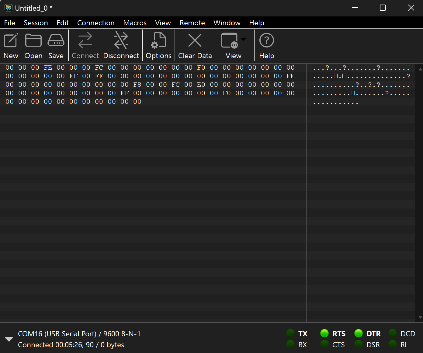
실패
Made By Minseok KIM
'VerilogHDL > Study' 카테고리의 다른 글
| [VerilogHDL] UART Rx, Tx 최종(Oversampling) (0) | 2024.05.22 |
|---|---|
| [VerilogHDL] UART Tx(2) (0) | 2024.05.22 |
| [VerilogHDL] FSM 코딩(Moore, Mealy) - 버튼, UpCounter (0) | 2024.05.19 |
| [VerilogHDL] 조합 논리 회로 & 순차 논리 회로, Latch & FlipFlop (0) | 2024.05.19 |
| [VerilogHDL] C&Verilog차이, SystemVerilog 기본, 8bit Adder FND, 만진 카운터 (0) | 2024.05.16 |
Let's Be Happy!
도움이 되었으면 좋겠어요 :)
![[VerilogHDL] UART Rx, Tx 최종(Oversampling)](https://img1.daumcdn.net/thumb/R750x0/?scode=mtistory2&fname=https%3A%2F%2Fblog.kakaocdn.net%2Fdn%2Fwwwzo%2FbtsHxROxdme%2FpdIwJALpcyo0k4O8hcZQWk%2Fimg.png)
![[VerilogHDL] UART Tx(2)](https://img1.daumcdn.net/thumb/R750x0/?scode=mtistory2&fname=https%3A%2F%2Fblog.kakaocdn.net%2Fdn%2FdbaZel%2FbtsHy64Ly4N%2FmIatgrSSpUGSRtYPcsihE1%2Fimg.png)
![[VerilogHDL] FSM 코딩(Moore, Mealy) - 버튼, UpCounter](https://img1.daumcdn.net/thumb/R750x0/?scode=mtistory2&fname=https%3A%2F%2Fblog.kakaocdn.net%2Fdn%2Fbetzc8%2FbtsHvuRSMN0%2FQWuDHrBhsfysBOnJnirWy1%2Fimg.png)
![[VerilogHDL] 조합 논리 회로 & 순차 논리 회로, Latch & FlipFlop](https://img1.daumcdn.net/thumb/R750x0/?scode=mtistory2&fname=https%3A%2F%2Fblog.kakaocdn.net%2Fdn%2FSF2r6%2FbtsHtOdeWqq%2Fj9KnstjOc4HKyuyYtH1lA0%2Fimg.png)